Step Down Converter Circuit Diagram
Boost converter diagram dc simple circuit topology conduction voltage converters mode discontinuous analysis schematic engineering output equilibrium four help astable Dc step 5v converter 4v circuit schematic volt output electronics lab driver led volts extremely converting voltages low current Schematic diagram of a basic step-up converter integrated in a
Schematic diagram of a basic Step-Up converter integrated in a
Converter step down dc circuit uc3845 buck boost using schematics circuits Compact switching step-down converter by max639 circuit diagram Making a step-down dc to dc converter using tps54331 chip
48v circuit buck regulator converter 30ma 9v existing cooling circuitlab engineering stack
2.4v to 5v step up dc-dc converterDc converter step down buck regulator simple question current voltage switch closed load stack Dc to dc boost converter circuit homemadeDiy dc to dc buck converter (step down).
Smps transistor circuits วงจร การ คอน เว อร เต อรDc dc converter 500 circuits: step-down converter (mc34063a) circuitConverter schematic chip voltage.

Inverter circuit: frequency converter circuit using mc3406a
Pcb hacksterRegulator switching dc to dc step down voltage with lm2596 Step up down dcAdp1821 step down dc-to-dc converter – electronic circuit diagram.
Down step converter switching compact circuits voltage circuit power 5v gr next switch supplies modeBuck converter design; selecting the input capacitance ripple voltage Circuits apmilifier: lt3433 based step up/step down dc to dc converterStep-down converter controller circuit diagram.

Circuit converter step down diagram controller circuits build dc schematic power supply current
Simple 12v to 24v step up converter circuit using tda2004Converter circuit elec circuits input Many circuits: dc to dc converter 2Dc step converter down circuit diagram 2010 pwm circuits rend august gr next synchronous.
Dc converter step down circuit diagram ac power schematics diagrams supply output electronic gr next common suppliesLm2596 regulator voltage switching datasheet eleccircuit regulators Low-voltage step-down converter schematic circuit diagramStep dc circuit down converter diagram based 12v 8v explanation.

Boost converter dc diagram circuit input step schematic electronoobs output circuitos make homemade using feedback component boots choose board steady
Dc converter circuit step using boost diagram 24v 12v simple volt 24 voltage power circuits supply output ic wiring mosfetVoltage schematic converter advantages Circuit converter using frequency.
.


Regulator switching DC to DC step down Voltage with LM2596

buck converter design; selecting the input capacitance ripple voltage

Low-Voltage Step-Down Converter Schematic Circuit Diagram

Simple 12V to 24V step up converter circuit using TDA2004 | ElecCircuit

ADP1821 Step Down DC-to-DC Converter – Electronic Circuit Diagram
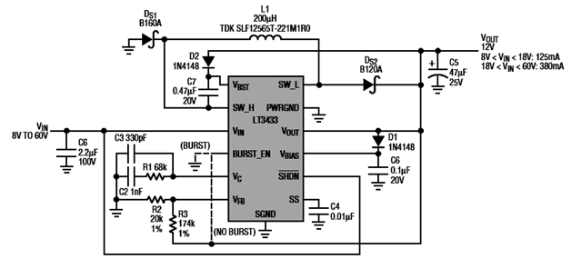
Circuits Apmilifier: LT3433 based Step Up/Step Down DC to DC Converter

DIY DC to DC Buck Converter (Step Down) - Hackster.io

DC to DC boost converter circuit homemade